Data Collection
Data Collection
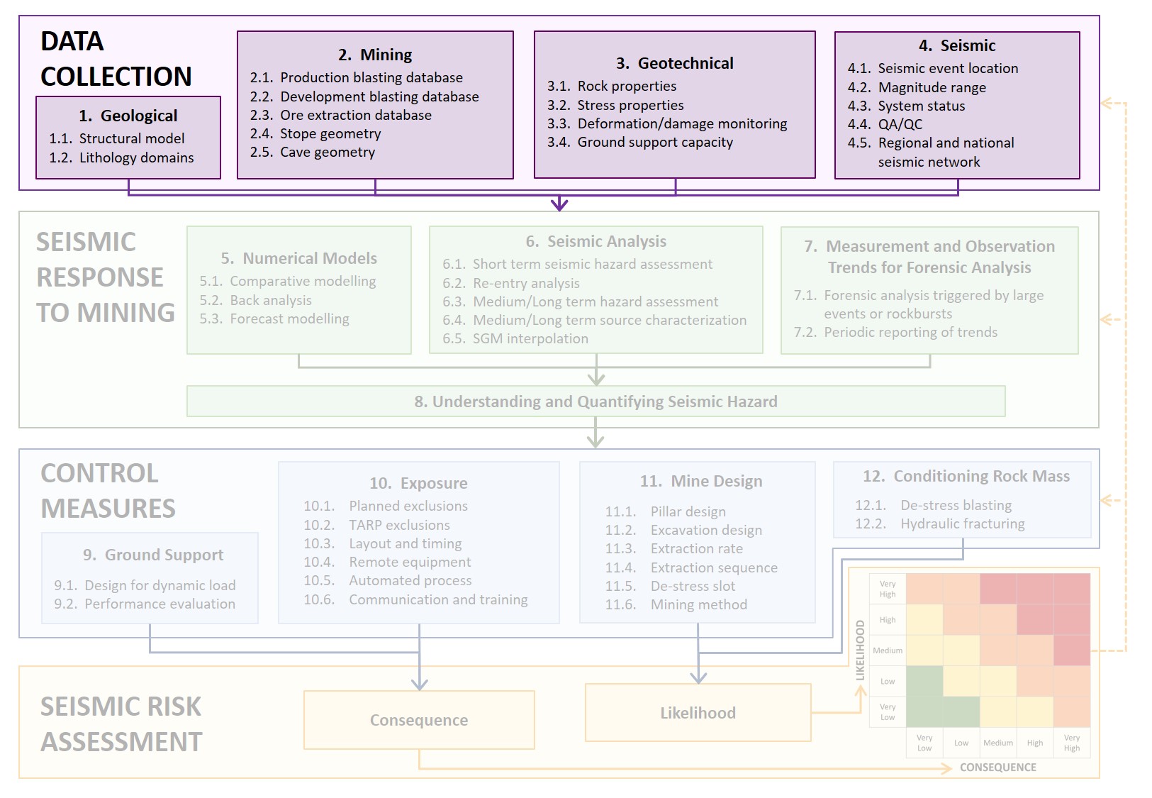
The purple area (Figure 2) of activities in the flowchart indicates the critical data required for seismic risk management. With the exception of seismic data, all other data is generally available in some form at most mine sites. The advanced practice in data collection will have a wide range of data, properly organised in databases with good visualisation, facilitating easy access and regular uses in multiple analyses across all databases.
 Figure2 Flowchart of the seismic risk management process emphasising the data collection activities
Gap # 1
|
GAP #1; Seismic monitoring: Mines are limited in terms of the number of seismic monitoring sensors they can install due to cost, access and data generated by each sensor. Ideally, a very dense array of sensors would enable greater data precision and open new and improved techniques to manage seismic risks. How to fil the gap: New development in hardware and automation of seismic data processing. |
1. Data collection - geological
The spatial variation of seismic hazard in most mines is often linked with geology; either geological structures or the nature of the geological units. This makes the collection and verification of geological data important for investigating seismic source mechanisms and anticipating the response to mining in new areas.
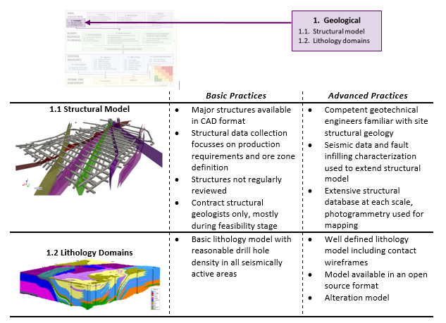
1.1.1 Structural model - basic
A lot of structural geology work is completed during the feasibility stage of mining operations, often by contract or consultant structural geologists. Generally, limited time is devoted to maintaining and developing the structural database during the operational phase of mining. Structural geologists are not always employed on a full-time basis and the focus on structural geology is usually production-centred, related to major structures that affect the ore zone. This sometimes leads to missing information on structures relevant to seismic risk management strategies. When the majority of the structural geology work is performed by outside contractors or consultants, this can leave the intimate understanding of the physical nature and behaviour of structures out of the reach of onsite personnel. Modelled structures are generally kept in a 3D wireframe format that can be used in the relevant mining and seismic analysis software. This often does not include small to medium scale structures below 100 m in extent. As mining progresses, it is common for structures to be extrapolated beyond the extent of the original interpretation. Often, new development areas are expected to intersect major structures, but the anticipated conditions are not observed. This leads to uncertainty in the reliability of the structural model.
1.1.2 Structural model - advanced
Mining operations with advanced structural geology practices emphasise data collection, interpretation and validation as a core focus of the geology department. Geotechnical engineers have competence in geology and are intimately familiar with the nature and response of each structure in the database. Aside from structural mapping, some operations use seismic data to interpret unmapped structures. This does require dense 3D seismic arrays, since some less accurate arrays commonly result in linear and/or planar system artefacts that can be falsely interpreted as geological structures. Structural interpretations from seismic data may also be used to increase the extent of mapped structures or to better understand their response to mining. It is important that the seismically interpreted structural information in the database is:
- identifiable and distinct from physically mapped structures to reflect the relative uncertainty; and
- reviewed/approved by geologists.
When relevant, the structural model also includes minor and intermediate scale structures that may only be operative in drive scale mechanisms. Smaller scale structures are not modelled explicitly, but the key characteristics are logged and recorded such as dip, dip direction and persistence. This is important for input into various stability assessments and advanced numerical models. Models that utilise discrete fracture networks (DFNs, Figure 3) are normally generated from the structural database according to the distributions of mapped orientations and extents. Digital photogrammetry (Figure 3) is used at many operations to facilitate the mapping of drive scale structures. This is especially useful for operations where in-cycle fibre-reinforced shotcrete is extensively used.


