
2. Mining: Difference between revisions
No edit summary |
No edit summary |
||
| (2 intermediate revisions by one other user not shown) | |||
| Line 1: | Line 1: | ||
__NOTOC__ | |||
[[File:1.02_Mining.jpg|500px|left|link=]] | [[File:1.02_Mining.jpg|500px|left|link=]] | ||
| Line 6: | Line 8: | ||
|- | |- | ||
| | | | ||
| | |Standard Practices | ||
|Advanced Properties | |Advanced Properties | ||
|- | |- | ||
|2.1 Production Blasting Database | |2.1 Production Blasting Database | ||
[[File:Production Blasting Database.png|150px|link=]] | [[File:Production Blasting Database.png|150px|link=]] | ||
| | | | ||
* Production blasts are recorded but not stored in an accessible database format | |||
* Blast location is a description only and not XYZ | |||
* Formatted blast database kept for major firings in seismically active areas only | |||
|<ul><li>All production firings kept in an accessible database format</li> | |||
<li>Blast details include accurate time and location XYZ, tonnage</li> | <li>Blast details include accurate time and location XYZ, tonnage</li> | ||
<li>More details for blast type kept to assess whether specific blasting practices influence seismic response</li> | <li>More details for blast type kept to assess whether specific blasting practices influence seismic response</li></ul> | ||
|- | |- | ||
|2.2 Development Blasting Database | |2.2 Development Blasting Database | ||
[[File:Development Blasting Database.png|150px|link=]] | [[File:Development Blasting Database.png|150px|link=]] | ||
|<li>Development blasting is not recorded other than | |<li>Development blasting is not recorded other than standard shift notes and logs</li> | ||
|<li>Development blasts are recorded along with production blasts, including accurate time and location XYZ</li> | |<li>Development blasts are recorded along with production blasts, including accurate time and location XYZ</li> | ||
<li>Development blasts may be recorded for the whole mine or only seismically active areas</li> | <li>Development blasts may be recorded for the whole mine or only seismically active areas</li> | ||
| Line 26: | Line 29: | ||
|2.3 Ore Extraction Database | |2.3 Ore Extraction Database | ||
[[File:Ore Extraction Database.png|150px|link=]] | [[File:Ore Extraction Database.png|150px|link=]] | ||
|<li>Production bogging is not recorded other than | |<li>Production bogging is not recorded other than standard shift logs</li> | ||
|<li>Production bogging records are kept in a single file with regular formatting</li> | |<li>Production bogging records are kept in a single file with regular formatting</li> | ||
<li>Details include time (accurate to the shift), location XYZ and tonnes</li> | <li>Details include time (accurate to the shift), location XYZ and tonnes</li> | ||
| Line 50: | Line 53: | ||
== 2.1 Production blasting database == | == 2.1 Production blasting database == | ||
=== 2.1.1 | === 2.1.1 Standard === | ||
When a blast, or a sequence of blasts is taken, voids are created and there is a disturbance in the local stress conditions. It is these changes in the stress conditions which could drive the violent failure of the surrounding rock mass. | When a blast, or a sequence of blasts is taken, voids are created and there is a disturbance in the local stress conditions. It is these changes in the stress conditions which could drive the violent failure of the surrounding rock mass. | ||
| Line 67: | Line 70: | ||
== 2.2 Development blasting database == | == 2.2 Development blasting database == | ||
=== 2.2.1 | === 2.2.1 Standard === | ||
The blasted volumes for drives are smaller than for stopes, but taken more regularly. The exposure of personnel is higher. Specifically, strain bursting can pose an important risk to the safety of mine personnel. As a | The blasted volumes for drives are smaller than for stopes, but taken more regularly. The exposure of personnel is higher. Specifically, strain bursting can pose an important risk to the safety of mine personnel. As a standard practice, a database of approximate time and location of development blasts must be maintained. | ||
=== 2.2.2 Advanced === | === 2.2.2 Advanced === | ||
| Line 81: | Line 84: | ||
== 2.3 Ore extraction database == | == 2.3 Ore extraction database == | ||
=== 2.3.1 | === 2.3.1 Standard === | ||
In caving and other mining methods, where the primary form of ore extraction is not reliant on the production blasting, the recording of the removal of rock (extraction data) may be an important driver of seismicity. A database of bogging data which includes time, tonnes and drawbell name/coordinate can be vital in understanding the seismic response. | In caving and other mining methods, where the primary form of ore extraction is not reliant on the production blasting, the recording of the removal of rock (extraction data) may be an important driver of seismicity. A database of bogging data which includes time, tonnes and drawbell name/coordinate can be vital in understanding the seismic response. | ||
| Line 87: | Line 90: | ||
=== 2.3.2 Advanced === | === 2.3.2 Advanced === | ||
Advanced extraction databases only differ from the | Advanced extraction databases only differ from the standard by having advanced graphics capabilities and ease of interaction with other databases to facilitate investigations and analyses. | ||
== 2.4 Stope geometry == | == 2.4 Stope geometry == | ||
=== 2.4.1 | === 2.4.1 Standard === | ||
Records of current voids and filled stopes are kept for a number of purposes, including back analysing seismic activities. Historical mining sequence is generally available, but seldom easily accessible. Planned and scheduled future stopes layout is also generally available and could be used for forecasting seismic hazard. | Records of current voids and filled stopes are kept for a number of purposes, including back analysing seismic activities. Historical mining sequence is generally available, but seldom easily accessible. Planned and scheduled future stopes layout is also generally available and could be used for forecasting seismic hazard. | ||
| Line 103: | Line 106: | ||
=== 2.4.2 Advanced === | === 2.4.2 Advanced === | ||
An advanced stope geometry database would contain data on voids (CMS), filled stopes (type of fill and dates), and orepasses deterioration at any point in time in the past. Advanced stope geometry would also differ from the | An advanced stope geometry database would contain data on voids (CMS), filled stopes (type of fill and dates), and orepasses deterioration at any point in time in the past. Advanced stope geometry would also differ from the Standard (2.4.1) by having accurate data, advanced graphics capabilities and ease of interaction with other databases to facilitate investigations and analyses. | ||
== 2.5 Cave geometry == | == 2.5 Cave geometry == | ||
=== 2.5.1 | === 2.5.1 Standard === | ||
For mining methods reliant on the formation of a cave, it is important to know the void geometry. Since access to the void is not possible, several indirect measurement methods are interpreted to find the most likely cave geometry. The figure below shows the three most widely used methods for estimating the cave front location: the interpretation of borehole observation/camera data (a), the interpretation of seismic data (b), and the use of drawpoint extraction data (c). Generally, all these techniques are used together to find the best possible estimation of the cave front. Although these methods are useful and give reasonable results, there is always some uncertainty in the cave geometry. | For mining methods reliant on the formation of a cave, it is important to know the void geometry. Since access to the void is not possible, several indirect measurement methods are interpreted to find the most likely cave geometry. The figure below shows the three most widely used methods for estimating the cave front location: the interpretation of borehole observation/camera data (a), the interpretation of seismic data (b), and the use of drawpoint extraction data (c). Generally, all these techniques are used together to find the best possible estimation of the cave front. Although these methods are useful and give reasonable results, there is always some uncertainty in the cave geometry. | ||
| Line 117: | Line 120: | ||
=== 2.5.2 Advanced === | === 2.5.2 Advanced === | ||
Recently, smart markers and magnetic beacons have been developed to track the flow and movement of rocks in the cave, as shown in the figure below. Smart markers are installed prior to the caving process and are designed to communicate with each other, which makes it possible to determine their relative position to each other. Magnetic beacons are also installed ahead of the cave and send a magnetic signal through the rock mass. These signals are registered on sensors which are installed throughout the mine which allows calculation of the three-dimensional position of the magnetic beacons. This allows real-time mapping of material movement. In addition to the | Recently, smart markers and magnetic beacons have been developed to track the flow and movement of rocks in the cave, as shown in the figure below. Smart markers are installed prior to the caving process and are designed to communicate with each other, which makes it possible to determine their relative position to each other. Magnetic beacons are also installed ahead of the cave and send a magnetic signal through the rock mass. These signals are registered on sensors which are installed throughout the mine which allows calculation of the three-dimensional position of the magnetic beacons. This allows real-time mapping of material movement. In addition to the standard techniques discussed in the previous sub-section, smart marker and magnetic beacon information will assist in interpreting the approximate caving front. | ||
[[File:Figure 8.png|link=]] | [[File:Figure 8.png|link=]] | ||
Latest revision as of 10:34, 18 June 2019
| Standard Practices | Advanced Properties | |
| 2.1 Production Blasting Database
|
|
|
| 2.2 Development Blasting Database
|
||
| 2.3 Ore Extraction Database
|
||
| 2.4 Stope Geometry
|
||
| 2.5 Cave Geometry
|
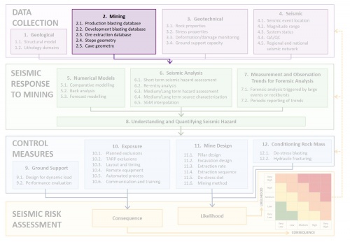
Mining activities are the major drivers of seismicity. It is well established that there is a strong correlation between mining and seismicity. Mining activities that are influencing the seismic response include production and development blasting, extraction rates and the geometry of excavations. Data needs to be readily available and organised to facilitate their use into the seismic risk management process.
2.1 Production blasting database
2.1.1 Standard
When a blast, or a sequence of blasts is taken, voids are created and there is a disturbance in the local stress conditions. It is these changes in the stress conditions which could drive the violent failure of the surrounding rock mass.
Production blasts are always recorded in some form by the mining department, but keeping exact coordinates is less common. The large effort involved in assigning accurate coordinates is usually the main reason for not keeping an extensive blast database. Blast events may also be identified and tagged during seismic processing, but the calculated locations are often unreliable.
2.1.2 Advanced
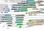
For operations where the seismic reaction to production blasts is severe, more detail and accuracy is required in the production blast database. The exact time, location (X,Y,Z), tonnes of explosive used, the blast type (rise, slot, primary or secondary stopes, undercut, drawbell) is carefully recorded in advanced practice. The figure below shows an advanced database identifying type of blast. All blasting data is stored and is easily retrievable.
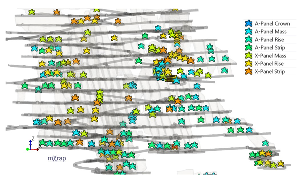
Figure: Advanced blast database showing individual stope blast, and type of blast
2.2 Development blasting database
2.2.1 Standard
The blasted volumes for drives are smaller than for stopes, but taken more regularly. The exposure of personnel is higher. Specifically, strain bursting can pose an important risk to the safety of mine personnel. As a standard practice, a database of approximate time and location of development blasts must be maintained.
2.2.2 Advanced
Advanced practice requires the time and coordinates to be recorded for all development blasts. Some details about the type of drive or other relevant information can be added to the database. The figure below is an example of a development blast database within a geologically complex rock mass. Such information can easily be used for back analysis, or investigations of anomalous rock mass response; for example, development blasting that triggers a remote response on a geological structure.
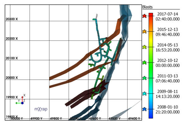
Figure: Development blast database for a mine with complex geological conditions
2.3 Ore extraction database
2.3.1 Standard
In caving and other mining methods, where the primary form of ore extraction is not reliant on the production blasting, the recording of the removal of rock (extraction data) may be an important driver of seismicity. A database of bogging data which includes time, tonnes and drawbell name/coordinate can be vital in understanding the seismic response.
2.3.2 Advanced
Advanced extraction databases only differ from the standard by having advanced graphics capabilities and ease of interaction with other databases to facilitate investigations and analyses.
2.4 Stope geometry
2.4.1 Standard
Records of current voids and filled stopes are kept for a number of purposes, including back analysing seismic activities. Historical mining sequence is generally available, but seldom easily accessible. Planned and scheduled future stopes layout is also generally available and could be used for forecasting seismic hazard.
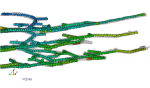
As shown in the figure below, the use of CMS is widespread and offers an accurate record of stope geometry and volumes.
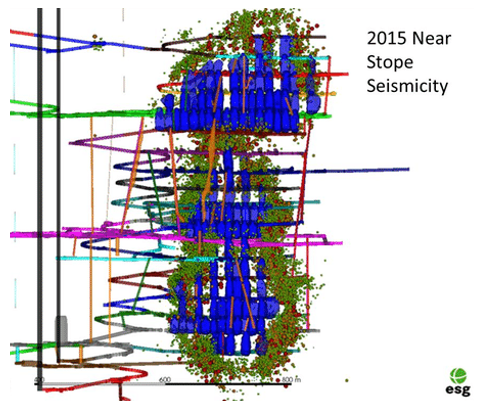
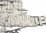
Figure: Extracted stope geometry overlaid with mine seismic record (Butler and Simser 2016)
2.4.2 Advanced
An advanced stope geometry database would contain data on voids (CMS), filled stopes (type of fill and dates), and orepasses deterioration at any point in time in the past. Advanced stope geometry would also differ from the Standard (2.4.1) by having accurate data, advanced graphics capabilities and ease of interaction with other databases to facilitate investigations and analyses.
2.5 Cave geometry
2.5.1 Standard
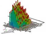
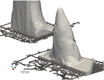
For mining methods reliant on the formation of a cave, it is important to know the void geometry. Since access to the void is not possible, several indirect measurement methods are interpreted to find the most likely cave geometry. The figure below shows the three most widely used methods for estimating the cave front location: the interpretation of borehole observation/camera data (a), the interpretation of seismic data (b), and the use of drawpoint extraction data (c). Generally, all these techniques are used together to find the best possible estimation of the cave front. Although these methods are useful and give reasonable results, there is always some uncertainty in the cave geometry.
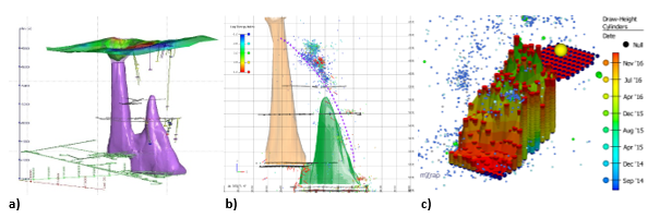
Figure: Typical methods used for the estimation of the cave front
2.5.2 Advanced
Recently, smart markers and magnetic beacons have been developed to track the flow and movement of rocks in the cave, as shown in the figure below. Smart markers are installed prior to the caving process and are designed to communicate with each other, which makes it possible to determine their relative position to each other. Magnetic beacons are also installed ahead of the cave and send a magnetic signal through the rock mass. These signals are registered on sensors which are installed throughout the mine which allows calculation of the three-dimensional position of the magnetic beacons. This allows real-time mapping of material movement. In addition to the standard techniques discussed in the previous sub-section, smart marker and magnetic beacon information will assist in interpreting the approximate caving front.
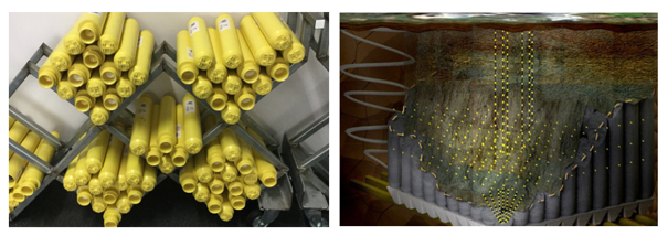
Figure: Smart Markers (left) and illustration of marker visualisation (right) (Elexon Electronics)